Wednesday, 13 May 2015

FYP 2 - Week 14(2) *Industry day*

FINAL YEAR PROJECT PRESENTATION

The Presentation Day has been a successfully finish. I have presented my project to both of the assigned accessors and they are satisfied with my project.
  • Venue: Gemilang Hall
  • 13 May 2015 
  • Wednesday
  • Time: 8.00am – 12.00pm (FYP 2 Degree Presentation)
  • 8.00am (booth and poster setup)
  •  All students of FYP 2 must register first before assessors are coming 9.00am (assess begins)


Now I have to write the FINAL REPORT for the Final Year Project which I must submit before Friday of week 15.

Monday, 11 May 2015

FYP 2 - Week 14

PREPARATION FOR INDUSTRY DAY AND PRINT POSTER

  • Test again the whole project system to make sure everything runs smoothly.
  • Study all the components function that related with the project.
  • Provide some examples of questions that will be asked by the assessors
  • Size of poster required is A1 measurement
  • The cost of printing is RM37 include GSt


Below is the demo for my project


Thursday, 7 May 2015

FYP 2 - Week 13

CREATE A POSTER 

  1. Create a poster by using a power point that provided by UNIKL BMI FYP blog, i just edit it from there.
  2. Size poster requirement for presentation is A1
  3. Below is picture I had done for my poster
  4. Also in this week, I also do draft report for chapter 4 and 5, I submit it to my supervisor for approval.


Thursday, 30 April 2015

FYP 2 - Week 12

MAKE LIST FOR POSTER REQUIREMENT IN PRESENTATION


Before making a poster, I have seen some examples of posters available at FYP blog, I just fill the poster before print it. among requirement that must be follow is:

  • Project Title
  • Student’s name
  • ID Student
  • Programme
  • Supervisor’s name
  • objective
  • project description
  • methodology
  • flowchart
  • result
  • conclusion
  • reference


Saturday, 25 April 2015

FYP 2 - Week 11

TESTING PROJECT

This is a result of the overall project after all testing, development and design finally has been successfully build and completed. This system can be used for house, office that used for door lock security using fingerprint. From picture below it shows when I has been successfully register or enroll the thumbprint and ready to access the house to access the system.


Fingerprint scanning to access the house

After the scanning fingerprint, the fingerprint sensor will identify and will process send to Arduino and will trigger solenoid to unlock the door, if not, the solenoid will lock until it gets a right thumbprint.

From picture below it shown the solenoid before scanning fingerprint the solenoid will lock and after the fingerprint the solenoid will unlock. It means, when a door via a solenoid, it is using basic electromagnetic forces to control the lock. The solenoid fits in the locking mechanism and, when locked, will expand so the device cannot be unlocked by sheer force. An electromagnetic force, such as a keycard, is needed to tell the solenoid to move, allowing the device to unlock and open.

Solenoid will lock before fingerprint scanning happen
Solenoid will unlock after successfully scanning


While the locking solenoid will keep the device locked, it is not technically on when in locking mode, because no power is being used. The solenoid only needs power when unlocking and, because most devices are consistently locked, very little energy is ever required by the solenoid. For this reason, most solenoids run on battery power, and the battery rarely needs to be changed, but in this project, the supply adapter is used for that battery.


After the fingerprint a solenoid process, the data fingerprint that user scan fingerprint from figure 4.10 will send to android application which is web server. Web servers are computers that deliver (serves up) Web pages. Every Web server has an IP address and possibly a domain name. For example, if users enter the URL http://192.168.0.2 in browser, this sends a request to the Web server whose domain name is 192.168.0.2. The server then fetches the page named 192.168.0.2 and sends it to browser.


After fingerprint scanning, the data will sent to android application to show I access the system

It shown the data user when I scanning fingerprint to enter the system. With this, I can only access that IP address from home. This means I must be connected to the same router that user has Ethernet shield is connected to. That picture is from I accessing webserver with my Android Smartphone.

Thursday, 16 April 2015

FYP 2 - Week 10

MAKE MODIFICATION THE HOUSE PROTOTYPE TO MAKE MORE ATTRACTIVE


The modifications are:
  • windows to make it like a real house
  • Create a door
  • Modified on the roof


Front House

the back house

Friday, 10 April 2015

FYP 2 - Week 9

BUILDING A PROTOTYPE OF FYP PROJECT


Steps of building a prototype 
  • Find some design example of house on the internet. 
  • The concept of the house will be in brown and white theme to make it more attractive.
  • Can buy the materials at bookstore
  • Next, design a wall for the front and the back of the house
  • Make a base for put a project
  • Lastly, make a roof and the roof is removable.


Cardboard brown and white

Cutting the white board for house

After cutting it

Glue it

Make a base for the house

The house is complete


Saturday, 4 April 2015

FYP 2 - Week 8(2)

TESTING FINGERPRINT 


First, download the Adafruit Fingerprint sensor library from github. To download click the ZIP button in the top bar, rename the uncompressed folder Adafruit_Fingerprint. Check that the Adafruit_Fingerprint folder contains Adafruit_Fingerprint.cpp and Adafruit_Fingerprint.h Place the Adafruit_Fingerprint library folder your /libraries/ folder. Users may need to create the libraries subfolder if it‟s first library. Restart the IDE.

Once we have restarted and we should be able to select the File→Examples→Adafruit_Fingerprint→fingerprint example sketch. Upload it to Arduino as usual. Open up the serial monitor at 9600 baud and when prompted place the finger against the sensor that was already enrolled.


You should see the following:


The 'confidence' is a score number (from 0 to 255) that indicates how good of a match the print is, higher is better. Note that if it matches at all, that means the sensor is pretty confident so you don't have to pay attention to the confidence number unless it makes sense for high security applications.

If you want to have a more detailed report, change the loop() to run getFingerprintID() instead of getFingerprintIDez() - that will give you a detailed report of exactly what the sensor is detecting at each point of the search process.

We did put together a simple sketch for enrolling a new finger via Arduino - its not as easy to use as the Windows program but it does work. Run the File→Examples→Adafruit_Fingerprint→enroll sketch and upload it to the Arduino, use the same wiring as above.


When you open up the serial monitor, it will ask for you to type in the ID to enroll - use the box up top to type in a number and click Send.


Then go through the enrollment process as indicated. When it has successfully enrolled a finger, it will print Stored!


Don't forget to do a search test when you're done enrolling to make sure its all good!

Thursday, 2 April 2015

FYP 2 - Week 8

DIFFERENCES BETWEEN ARDUINO AND RASPBERRY PI?


Arduino uses a microcontroller; Raspberry Pi uses an applications processor. There are some things a Raspberry Pi is better for, and loads of things an Arduino is more suited to. There’s a good potential between the Arduinos you might have in your at home, and your Raspberry Pi, which you can use to drive them.

The Arduino UNO is a microcontroller based physical computing platform. The Rasperry Pi is a microprocessor based single-board computer (SBC). The Arduino and the Raspberry Pi are more directly comparable in terms of form and function.

What that means in practical terms is mostly about S/W development:
  • The nice thing about the microprocessor based Raspberry Pi / Arduino Due is that it is running linux.  You can program for it in C++, Java, python or some other language you may already be comfortable with.  You may indeed be able to take an application you already have and compile it to run on the Pi / Due without making any changes.
  • With the Arduino Uno (et al), you would need to create a sketch in the Arduino language.  This is not hard - it looks very C-like.  It is just something you have to do.  There are a ton of libraries and classes for Arduino - so it is possible to make it do just about anything a home fingerprint project might want.

They are both very capable for a home fingerprint project.  I would worry over

Friday, 27 March 2015

FYP2 - Week 7

WHY USING SOLENOID?


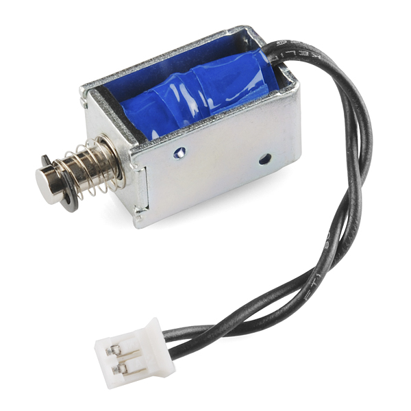
Solenoids are basically electromagnets: they are made of a big coil of copper wire with an armature (a slug of metal) in the middle. When the coil is energized, the slug is pulled into the center of the coil. This makes the solenoid able to pull from one end.

This solenoid in particular is nice and strong, and has a slug with a slanted cut and a good mounting bracket. It's basically an electronic lock, designed for a basic cabinet or safe or door. Normally the lock is active so you can't open the door because the solenoid slug is in the way. It does not use any power in this state. When 9-12VDC is applied, the slug pulls in so it doesn't stick out anymore and the door can be opened.

The solenoids come with the slanted slug as shown above, but you can open it with the two Phillips-head screws and turn it around so its rotated 90, 180 or 270 degrees so that it matches the door you want to use it with.

You will need a fairly good power supply to drive a solenoid, as a lot of current will rush into the solenoid to charge up the electro-magnet, about 500mA, so don't try to power it with a 9V battery!


TECHNICAL DETAILS
  • 24 DC operation (you can use 9-24 DC volts, but lower voltage results in weaker/slower operation)
  • Push or pull type with 5.5 mm throw
  • DC coil resistance: 100 ohms
  • 5 Newton starting force (24VDC)
  • 1.4 oz / 39 grams


When an electrical current is passed through the coils windings, it behaves like an electromagnet and the plunger, which is located inside the coil, is attracted towards the centre of the coil by the magnetic flux setup within the coils body, which in turn compresses a small spring attached to one end of the plunger. The force and speed of the plungers movement is determined by the strength of the magnetic flux generated within the coil.

When the supply current is turned “OFF” (de-energised) the electromagnetic field generated previously by the coil collapses and the energy stored in the compressed spring forces the plunger back out to its original rest position. This back and forth movement of the plunger is known as the solenoids “Stroke”, in other words the maximum distance the plunger can travel in either an “IN” or an “OUT” direction, for example, 0 – 30mm.


Linear solenoids are useful in many applications that require an open or closed (in or out) type motion such as electronically activated door locks, pneumatic or hydraulic control valves, robotics, automotive engine management, irrigation valves to water the garden and even the “Ding-Dong” door bell has one. They are available as open frame, closed frame or sealed tubular types.

Thursday, 12 March 2015

FYP2 - Week 6

TESTING CONTROLED LED AS SOLENOID IN ARDUINO WEB SERVER 


I wanted to investigate controlling the digital outputs on a Arduino from a webpage so I decided to build a simple setup to Turn a LED on and off from a webpage. For this project I used the Arduino Uno R3 and Arduino Ethernet Shield.


First off we need to configure the web server  this is done by calling the Ethernet libraries, setting the Mac Address, IP Address and Server Port. then in the Void Setup you start the server and define the pin you want to plug the LED into.

#include <SPI.h>
#include <Ethernet.h>

byte mac[] = { 0xDE, 0xAD, 0xBE, 0xEF, 0xFE, 0xED };
IPAddress ip(192,168,0, 2);

EthernetServer server(80);

void setup()
{
Serial.begin(9600);
pinMode(8, OUTPUT);
Ethernet.begin(mac, ip);
server.begin();

}

In the Void Loop we define client then check that the web server is connected and available the get it to display some HTML. The first lot checks the status of pin 8 and prints HTML to tell us if the LED is currently turned on or off. Then we use a HTML form to make some radio buttons and a submit button to select the status on or off.

if (digitalRead(8)){
client.print(” LED is <font color=’green’>ON</font>”);
}else{
client.print(” LED is <font color=’red’>OFF</font>”);
}
client.println(“<br />”);

client.print(“<FORM action=\”http://192.168.1.177/\” >”);
client.print(“<P> <INPUT type=\”radio\” name=\”status\” value=\”1\”>ON”);
client.print(“<P> <INPUT type=\”radio\” name=\”status\” value=\”0\”>OFF”);
client.print(“<P> <INPUT type=\”submit\” value=\”Submit\”> </FORM>”);

break;

}

Now all that is left is to read the input from the HTML Form and turn the led on or off. When you select one of the radio buttons and click submit the form adds a status=1 or status=0 to the end of the URL. We can now use the GET function to read the value and run through am IF statement to set the digital write on pin 8 to either High or Low (On or Off).

if (c == ‘\n’) {

currentLineIsBlank = true;
buffer=”";
} else if (c == ‘\r’) {
if(buffer.indexOf(“GET /?status=1″)>=0)
digitalWrite(8,HIGH);

if(buffer.indexOf(“GET /?status=0″)>=0)
digitalWrite(8,LOW);
}

else {
After create HTML form, the web server will look like this

Before click the on LED

After click the ON the LED in red led


Wednesday, 4 March 2015

FYP2 - Week 5

Briefing #1 FYP2 Degree

The briefing is about to give some explanation for the students who are taking the Final Year Project for Diploma and Degree programmed. The briefing is about:
  •  Introduction
  • Objectives
  • Credits and duration
  • Scope of projects
  • Title selection
  • Project Assessment
  • Presentation day
  •  Submission date of project

Wednesday, 25 February 2015

FYP2 - Week 4(2)

Result form previous post of SD Card
  • Copy the coding sketch in previous post and paste it into the Arduino IDE. 
  • Change the IP address in the sketch to match the IP address range of your network.
  • Your hardware must be set up as described in previous of this tutorial.
  • Load the sketch to the Arduino and then open a web browser on a computer that is connected to the same network as the Arduino.
  • Surf to the Arduino by typing the IP address of the Arduino into the URL field of the browser, e.g. 192.168.0.2 

The Web Server should display a web page as shown below.


Important Note!
  • If an uninitialized SD card is left in the SD card socket of the shield, it can cause problems with code in the sketch that is accessing the Ethernet chip. This may cause symptoms such as the sketch running once or twice, then hanging up.
  • This is because both the Ethernet chip and the SD card are accessed by the Arduino using the same SPI bus.
  • If the SD card is not being used with an Ethernet application, either remove it from the socket or add the following code to disable the SD card


Tuesday, 24 February 2015

FYP2 - Week 4

Test the SD card in the Ethernet shield

The Arduino Uno board and official Arduino Ethernet shield are used. The Ethernet shield contains the WIZnet W5100 Ethernet chip. To set up the hardware, first plug the Arduino Ethernet shield into the Arduino board and then plug a micro SD card into the SD card socket of the Ethernet shield. Power the Arduino from a USB cable plugged into the host PC computer.

The Arduino, Arduino Ethernet shield and micro SD card are used to make a web server that hosts a web page on the SD card. When a browser requests a web page from the Arduino web server, the Arduino will fetch the web page from the SD card.

Creating the Web Page
Because the web page is to be stored on the SD card, it must first be created using a text editor and then copied to the SD card.

Web Page
Create the following web page in a text editor. When you save the text file, give it the name: index.htm


<!DOCTYPE html>
<html>
    <head>
        <title>Arduino SD Card Web Page</title>
    </head>
    <body>
        <h1>Hello from the Arduino SD Card!</h1>
        <p>A web page from the Arduino SD card server.</p>
    </body>
</html>


Nothing new here, it is the same as the web page from the first web server in this tutorial with just the text changed. Test this web page by opening it in a web browser
.
Copying the Web Page
You will need a micro SD card slot on your computer or a card reader that is capable of reading and writing a micro SD card.

Insert the micro SD card into the slot on the computer or card reader that is plugged into the computer and copy the index.htm file to the micro SD card.

Now plug the SD card into the micro SD card slot on the Ethernet shield.


SD Card Web Server

Hardware
You should now have the micro SD card with web page copied to it inserted into the card slot on the Arduino Ethernet shield. The Ethernet shield should be plugged into a compatible Arduino and into an Ethernet cable connected to your network. The Arduino / Ethernet shield should be powered from a USB cable.

Arduino Sketch
The Arduino sketch that fetches the web page from the SD card and sends it to the browser is shown below.


#include <SPI.h>
#include <Ethernet.h>
#include <SD.h>

// MAC address from Ethernet shield sticker under board
byte mac[] = { 0xDE, 0xAD, 0xBE, 0xEF, 0xFE, 0xED };
IPAddress ip(192, 168, 0, 2); // IP address, may need to change depending on network
EthernetServer server(80);  // create a server at port 80

File webFile;

void setup()
{
    Ethernet.begin(mac, ip);  // initialize Ethernet device
    server.begin();           // start to listen for clients
    Serial.begin(9600);       // for debugging
   
    // initialize SD card
    Serial.println("Initializing SD card...");
    if (!SD.begin(4)) {
        Serial.println("ERROR - SD card initialization failed!");
        return;    // init failed
    }
    Serial.println("SUCCESS - SD card initialized.");
    // check for index.htm file
    if (!SD.exists("index.htm")) {
        Serial.println("ERROR - Can't find index.htm file!");
        return;  // can't find index file
    }
    Serial.println("SUCCESS - Found index.htm file.");
}

void loop()
{
    EthernetClient client = server.available();  // try to get client

    if (client) {  // got client?
        boolean currentLineIsBlank = true;
        while (client.connected()) {
            if (client.available()) {   // client data available to read
                char c = client.read(); // read 1 byte (character) from client
                // last line of client request is blank and ends with \n
                // respond to client only after last line received
                if (c == '\n' && currentLineIsBlank) {
                    // send a standard http response header
                    client.println("HTTP/1.1 200 OK");
                    client.println("Content-Type: text/html");
                    client.println("Connection: close");
                    client.println();
                    // send web page
                    webFile = SD.open("index.htm");        // open web page file
                    if (webFile) {
                        while(webFile.available()) {
                            client.write(webFile.read()); // send web page to client
                        }
                        webFile.close();
                    }
                    break;
                }
                // every line of text received from the client ends with \r\n
                if (c == '\n') {
                    // last character on line of received text
                    // starting new line with next character read
                    currentLineIsBlank = true;
                }
                else if (c != '\r') {
                    // a text character was received from client
                    currentLineIsBlank = false;
                }
            } // end if (client.available())
        } // end while (client.connected())
        delay(1);      // give the web browser time to receive the data
        client.stop(); // close the connection
    } // end if (client)
}


Using the Sketch
Copy the above sketch and paste it into the Arduino IDE. Load the sketch to the Arduino and then surf to the IP address set in the sketch with your web browser. The web page that you created should be displayed in the browser as it is served up by the Arduino SD card web server.